
Ohm’s Law is a fundamental principle in electrical engineering that relates the three essential quantities in an electrical circuit: voltage, current, and resistance. It states that the current flowing through a conductor is directly proportional to the voltage applied across it and inversely proportional to the resistance of the conductor.
Understanding is crucial for comprehending the behavior of electrical circuits and designing safe and efficient systems. It forms the basis for many electrical calculations and serves as a foundation for more advanced concepts in electrical engineering.
Relationship Between Voltage, Current, and Resistance
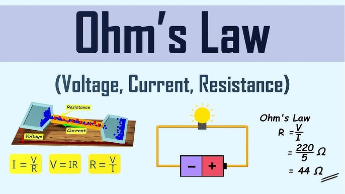
Ohms Law establishes a clear relationship between an electrical circuit’s voltage, current, and resistance. According to this law, the current (I) flowing through a conductor is equal to the voltage (V) across the conductor divided by its resistance (R), as expressed by the equation:
I = V / R
This equation implies that increasing the voltage will result in a larger current flow while increasing the resistance will decrease the current flow. It demonstrates the proportional and inverse relationship between these three quantities.
Understanding the relationship between voltage, current, and resistance is essential for analyzing and designing electrical circuits, as it allows engineers to predict the system’s behavior and make informed decisions regarding component selection and circuit optimization.
Water Pipe Analogy
A helpful analogy to understand Ohm’s Law is to compare it to the water flow in a pipe.
Just as increasing the water pressure results in a higher flow rate, increasing the voltage in an electrical circuit leads to a greater current flow. Similarly, a narrower or clogged pipe restricts water flow, just as higher resistance in a circuit limits the current.
This analogy helps visualize the concepts of voltage, current, and resistance and how they interact in a circuit. It provides a relatable and intuitive way to understand Ohm’s Law and its applications in electrical systems.
Experimental Verification
- Experimental verification of Ohm’s Law involves setting up a simple circuit and measuring the voltage, current, and resistance to confirm the relationship predicted by the law.
- To verify Ohm’s Law, one can construct a circuit with a known resistor and a variable power supply. By measuring the voltage across the resistor using a voltmeter and the current flowing through the resistor using an ammeter, one can calculate the resistance using this Law and compare it to the known value.
Ohm’s Law Magic Triangle
The Ohm’s Law Magic Triangle is a graphical representation that helps simplify calculations involving voltage, current, and resistance. It provides a visual aid for quickly determining the missing value in equation I = V / R.
The triangle has three sides representing voltage (V), current (I), and resistance (R).
Ohm’s Law Solved Problems
- Problem: Calculate the current flowing through a resistor with a voltage of 12 volts and a resistance of 4 ohms.
- Solution: Using Ohm’s Law (I = V / R), the current (I) can be calculated as I = 12 V / 4 Ω = 3 A.
- Problem: Determine the resistance required to limit the current to 0.5 amps when a voltage of 9 volts is applied.
- Solution: Rearranging Ohm’s Law to solve for resistance (R = V / I), the resistance (R) is calculated as R = 9 V / 0.5 A = 18 Ω.
Calculating Electrical Power
Ohm’s Law not only relates voltage, current, and resistance but also provides a way to calculate electrical power in a circuit. The power (P) in watts can be determined using the formula:
P = V × I
Where V is the voltage across the circuit or component, and I is the current flowing through it.
By multiplying the voltage and current, engineers can determine the power dissipated or consumed in a circuit. This calculation is essential for selecting appropriate components, designing power systems, and ensuring circuit safety.
Ohm’s Law Pie Chart
- An Ohm’s Law pie chart is a graphical representation that illustrates the relationship between voltage, current, and resistance in a circuit. It visually demonstrates the proportionality and inverse relationship between these quantities.
- The size of each sector corresponds to the magnitude of the respective quantity. For example, if the voltage is larger than the current, the voltage sector will be larger than the current sector.
Matrix Table
- A matrix table is a tabular representation that organizes different combinations of voltage, current, and resistance values according to this Law. It serves as a handy reference for performing calculations and understanding the relationships between these quantities.
- By locating the known values in the table, users can easily find the missing value using the corresponding formula.
- The matrix table simplifies calculations and eliminates the need for complex rearrangements of equations. It is a useful tool for both beginners and experienced engineers when working with this Law.
Applications
- Circuit Analysis: It is essential for analyzing electrical circuits, determining voltage drops, current distributions, and power dissipation, and verifying circuit behavior.
- Component Selection: Engineers use this Law to select resistors, capacitors, and other components based on desired voltage and current requirements.
- Power Calculations: By applying this Law, engineers can calculate power dissipation in resistors, and power consumption of electrical devices, and determine appropriate power ratings for components.
- Troubleshooting: It aids in diagnosing and troubleshooting electrical problems by analyzing voltage, current, and resistance measurements in circuits.
- Electrical Safety: Understanding this Law is crucial for ensuring electrical safety, preventing circuit overloads, and avoiding hazards caused by excessive current or voltage.
Limitations of Ohm’s Law
- Linearity: It assumes that the relationship between voltage, current, and resistance is linear. In reality, some components, such as diodes or transistors, may not follow this Law due to their nonlinear behavior.
- Temperature Dependency: It assumes constant resistance, but in some materials, resistance can vary with temperature. This can affect the accuracy of calculations in circuits with temperature-dependent resistors.
- Frequency Dependency – In AC circuits, additional considerations, such as impedance and reactance, come into play.
- Material Constraints: Non-ideal behavior of materials can introduce deviations from this Law.
Engineers must be aware of these limitations and consider them when working with non-ideal components or complex circuits.